PSpice Designer Plus

PSpice Circuit Simulator

Even experienced electronics developers can hardly predict the behavior of electrical circuits. Therefore, circuits or only critical circuit parts are analyzed either by physically constructed prototypes and subsequent measurements or by circuit simulations. The trend here is clearly towards virtually simulated measurement, as the development cycles are getting shorter and shorter, and simulations can be used very promptly to make statements that correlate with measurements. Worldwide, PSpice has been the reference simulator for years, and most component manufacturers offer PSpice simulation models on the Internet.

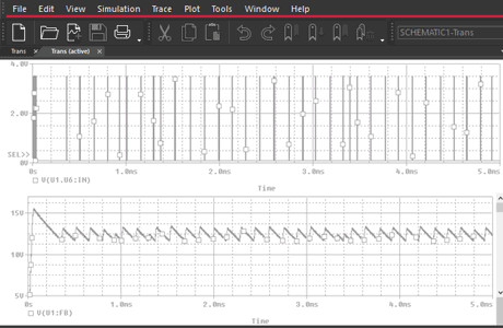
Based on the circuit diagram drawn for a PCB layout, a simulation can be started. If necessary, the user inserts a current source or a defined stimulus and measuring points in the circuit diagram. This procedure is similar to a physical setup with function generator and oscilloscope.
What's New in PSpice

PSpice Simulation Circuit Analysis

Analyze and verify your analog and mixed-signal electrical circuits with the advanced PSpice simulation tools in OrCAD.

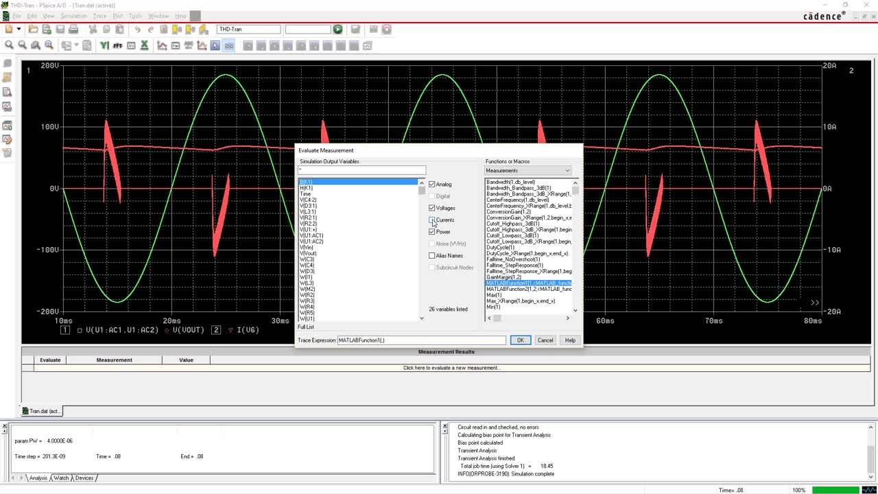
Validate Your Circuit Automatically Without Manually Plotting Graphs

Validate Your Circuit Automatically Without Manually Plotting Graphs

Virtually create and test designs before developing hardware, saving you time, money and materials.

Co-Simulate Mechanical and Electrical Systems

Co-Simulate Mechanical and Electrical Systems

The seamless bi-directional integration between MathWorks MATLAB / Simulink and PSpice lets you easily simulate electrical circuits and mechanical, hydraulic, thermal blocks in one unified environment.

Product Features

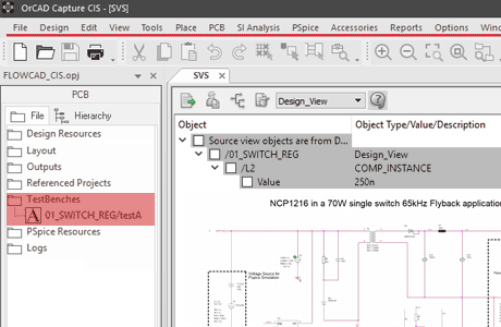
OrCAD Capture testbench for PSpice
Capture testbench for PSpice

OrCAD Capture Testbench for PSpice

OrCAD Capture is a schematic entry tool to capture the design intent of an electronic circuit. Schematics capture the netlist and drive later in the design process the layout of a PCB. During development OrCAD Capture can be used to run circuit simulations with PSpice. Select an area or the circuit and create a live copy as a testbench. Now you can apply voltages and probes for simulation on the virtual copy of the schematic. Optimization and documentation of wave forms stays in sync with the master schematic for the layout.

Sensitivity Analysis
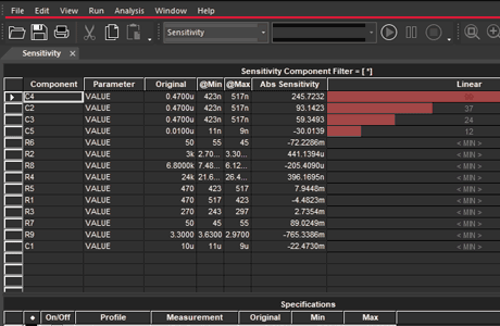
Display of sensitive components

Sensitivity Analysis

In this simulation variant, the sensitivity of all components of the circuit is calculated. Sensitivity indicates the relative influence of each component on one or more target functions of a circuit, such as e.g. maximum power, bandwidth, center frequency, etc. A graphical representation is available for evaluation. It shows the influence on the selected target function of the critical components, with regard to the component tolerance. This allows you to choose non-critical components with larger tolerances, while components where small changes in value have a major influence on the target functions are specifically specified with tight tolerances. This reduces costs at insensitive points. The worst case results for each specification is calculated as well.

Advanced Monte Carlo
Component parameter optimization

Optimizer

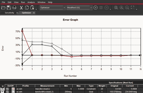
The optimizer function can independently dimension the components based on a given circuit (netlist) so that a target function is achieved as precisely as possible. Based on a defined objective function, the optimizer function not only calculates the theoretically optimal component values, e.g. R1 = 57.34 ohms and R2 = 14.29 ohms and ß = 129. It is also possible to specify specific component series from which the values may be selected as possible target results. For example, with an E24 series, the optimizer simulation would select values of R1 = 56 ohms and R2 = 22 ohms as a component combination for optimum target function.

Curve Fitting
Curve Fitting

Curve Fitting

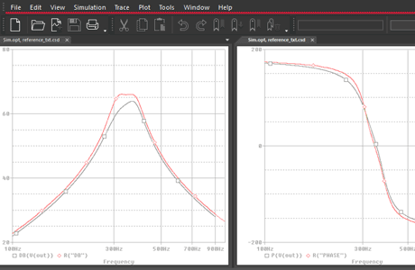
PSpice can optimize component parameters of a circuit to match a dedicated output curve. there are multiple applications, where this functionality is useful. When a component is obsolete and a redesign is required, the output curve must be identical. When there is no exact replacement the circuit must have additional components and the parameter for multiple components will be simulated until the curve is identical.

Parametric Plot
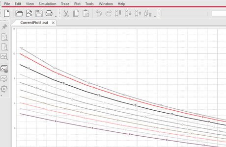
Curves of different parameter settings

Parametric Plot

The parametric plot sweeps multiple values at the same time in a nested structure. Once decided how the different parameters must be varied (for example voltage source from 0 volts to 10 volts with the step size 1 volt, a from 1 pF to 10 pF in steps 0.1 p and a resistor from 1 k to 1 meg in a logarithmic setup), the tool calculates the results for each specification and each combination of parameters possible. When it is done, you can quick plot so many curves as you want to analyze the behavior of your circuit. It is possible to dimension values for specifications like rise time, overshoot, power, bandwitdh, etc.

Global Tolerances
Global tolerances for all models

Global Tolerances

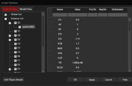
PSpice Advanced Analysis supports the assignment of global tolerances in PSpice models. In a PSpice circuit with freely available PSpice models, parameters for manufacturing tolerances can be specified centrally in the software. In a Monte Carlo simulation, the behavior of the circuit is then no longer simulated at exact values for resistors (eg 10 ohms), but component combinations with tolerances of ±5% can be performed for all resistors without the simulation models need to be adjusted. Tolerances can be given globally for resistors, capacitors, inductors, voltage and current sources. However, it is also possible to set specific tolerances for individual components in the software, for example D1 1N4148 and subcircuits.

DMI (Device Model Interface)

Device Model Interface

PSpice uses the DMI (Device Model Interface) to simulate complex circuit parts as virtual prototypes. For this purpose, the circuit parts with programming languages such as C / C ++, SystemC or Verilog-A are described in various levels of abstraction and the program code in PSpice is integrated via the Device Model Interface. Possible applications include Digital Power Supply (SMPS), FIR or Noise Filter or even Hardware in the Loop (HIL). The details are described in the Application Note .

Advanced Monte Carlo
Failure probability out of specification

Advanced Monte Carlo

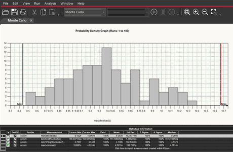
With Monte Carlo analysis, tolerance of components is varied using a guassian, an uniform or a self defined distribution. The result is a probability density graph where tolerances for each component are varied in each iteration to calculate value of each specification. So can be determined the different effects on the target functions. With this analysis, statements can be made as how high yield is, how many products would fail in quality assurance. Graphical representations can be used to detect weak points and the developer can specifically plan for quality and increase yield changing components with tight tolerances or absolutely redesigning the circuit. Monte Carlo analysis should be used together with Sensitivity analysis.

Product Feature Comparison for PSpice

    PSpice Designer PSpice Designer Plus PSpice System Designer
Analog circuit simulation
Digital circuit elements
OrCAD Capture -
OrCAD Capture CIS - -
Smoke Analysis
Systems Option -
Advanced Analysis -
Matlab Simulink co-simulation -
DMI Device Model Interface -
This table is for information only. For details consult the official Cadence datasheets.