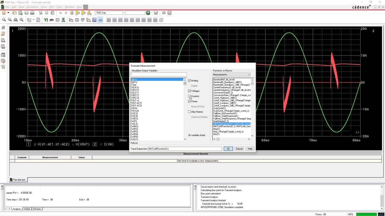
PSpice A/D

PSpice Circuit Simulator

Even experienced electronics developers can hardly predict the behavior of electrical circuits. Therefore, circuits or only critical circuit parts are analyzed either by physically constructed prototypes and subsequent measurements or by circuit simulations. The trend here is clearly towards virtually simulated measurement, as the development cycles are getting shorter and shorter, and simulations can be used very promptly to make statements that correlate with measurements. Worldwide, PSpice has been the reference simulator for years, and most component manufacturers offer PSpice simulation models on the Internet.

Based on the circuit diagram drawn for a PCB layout, a simulation can be started. If necessary, the user inserts a current source or a defined stimulus and measuring points in the circuit diagram. This procedure is similar to a physical setup with function generator and oscilloscope.

PSpice Simulation Circuit Analysis

Analyze and verify your analog and mixed-signal electrical circuits with the advanced PSpice simulation tools in OrCAD.

Validate Your Circuit Automatically Without Manually Plotting Graphs

Validate Your Circuit Automatically Without Manually Plotting Graphs

Virtually create and test designs before developing hardware, saving you time, money and materials.

Co-Simulate Mechanical and Electrical Systems

Co-Simulate Mechanical and Electrical Systems

The seamless bi-directional integration between MathWorks MATLAB / Simulink and PSpice lets you easily simulate electrical circuits and mechanical, hydraulic, thermal blocks in one unified environment.

Product Features

ABM Model
Behavior model of a control loop

ABM Model

Power electronics, operational amplifiers, torques of mechanical systems, as well to describe other analogy systems. Behavioral modeling allows to model a device or a system component representing its behavior. You can use it in the domain of analog simulation to model new device types and for black-box modeling of complex systems as the angular velocity of an electric controlled motor depending on the friction or PID controllers with Laplace blocks.

Auto Convergence
Selection for Auto Convergence

Auto Convergence

In circuits with high switching frequencies, fast rise times, large different time constants in a circuit or in mathematically described circuits, there may be convergence problems of a spice simulator, whereby the simulation can break off. PSpice has several internal simulation methods and can adjust the internal simulation parameters so that such abortions are avoided by internal process changes and correct results are calculated and displayed.

Magnetic Part Designer
Hysteresis curve of a ferrite core

Magnetic Part Designer

With the Magnetic Part Designer, magnetic components like power transformers, DC inductors, or different converters can be described in a simulation model. Here, the values (e.g. primary and secondary voltage, number of turns, manufacturer of the ferrite material, geometrical parameters, insulation material, maximum currents, etc.) are entered via a wizard. With PSpice simulation suitable variants can be selected. Subsequently, different cores (EI, UI) from the library can be compared in an analysis. Only with a few steps you get your desired magnetical part to be used in your system.

Mixed Mode
Simulation of an A/D converter

Mixed Mode Simulator

Digital and analog circuit parts can be mixed as desired in a PSpice simulation. The timing and propagation delay (min, max, typical, worst case) can be specified for digital circuit elements. PSpice can simulate the behavior of A/D converters, and abstract control logic can be integrated into analog circuits. Various sources can be chosen as stimuli for this purpose. The time-to-clock-out (TCO) behavior can be deposited in the model.

Power Electronic
Input and output curve for SMPS

Power Electronics

In power electronics, uncontrolled electrical energy is converted into the energy form required by the respective consumer or actuator with precisely defined currents, voltages and frequencies. The behavior of the P/N junction or the MOSFET technology is simulated. Thus, DC-DC converters, IGBTs, thyristors and switching power supplies (SMPS) can be predicted from the behavior and dimensioned and optimized accordingly for the circuit.

Frequency Response Analysis (FRA)
Frequency Response Analysis

Frequency Response Analysis (FRA)

A Frequency Response Analysis is mainly used to obtain a phase response of a non-linear circuit where voltages are switched and the operating points change at the same time. In this analysis, transient signals are injected into the current loop to be examined, and the frequency components are displayed after a Fourier analysis in a gain/phase response plot. This solves the problem of linearizing the AC sweep. In a simulation over time, with FRA, e.g. different gain factors. For an example, see your installation at ..\tools\pspice\capture_samples\anasim\fra.

Post Process
Post Process

Post Process

After a simulation the results can be visualized in the PSpice Waveform viewer. Since PSpice can save all values of the complete simulation, other measurement points or function data can be selected without having to restart the simulation. You can also evaluate your requirements and specifications using the calculated data with default or self-defined functions.

Model Creation
Model Creation

Model Creation

PSpice models can be created very quickly using values from a datasheet. Using various input masks, a few required component parameters and characteristic curves are queried so that a model can be generated quickly. Optimized input masks are available for capacitors, coils, switches, transformers, sources, diodes, IGBTs, MOSFETs, OPAMPs, etc.

IBIS Model Import
IBIS Model Import

IBIS Model Import

PSpice can directly import IBIS models in Model Editor and then generate corresponding PSpice models. All IBIS versions are supported. This is how the component behavior of drivers for digital signal transmission can be modeled. V-t curves are supported. An SI simulation in PSpice is possible, but the OrCAD or Sigrity SI tools are better suited to extract the trace structure of a transmission line.

Product Feature Comparison for PSpice

    PSpice A/D PSpice Designer PSpice Designer Plus Allegro PSpice System OrCAD PCB Designer Professional with PSpice
Analog circuit simulation
Digital circuit elements
OrCAD Capture - -
OrCAD Capture CIS - - - -
Smoke Analysis -
Systems Option - - -
Advanced Analysis - - -
Matlab Simulink co-simulation - - -
DMI Device Model Interface - - -
This table is for information only. For details consult the official datasheets from Cadence.