OrCAD Capture

OrCAD Capture Schematic

OrCAD Capture schematic entry tool for circuit diagrams is one of the world's most widely used software for entering and documenting electrical circuits. It is outstanding how simple and intuitive the design intentions are captured. OrCAD Capture uses flat or hierarchical circuit diagrams. Via the navigation window the different pages of the circuit diagram can be selected and thematically managed.

Using the PartBrowser, circuit diagram symbols are selected with the aid of filters from the library and placed in the circuit diagram. The electrical connections (networks) between the associated component pins can be quickly established. In the case of hierarchically structured designs, the same electrical networks are interconnected via cross-porting ports or defined as global networks.

Variants are defined in the schema editor and later output as variants with different parts lists for each variant. In OrCAD Capture assembly variants can be created with several logic functions for a PCB by different bill of materials for each variant. If programmed components are used in the circuit, pin assignments and signals from FPGAs from different manufacturers can be read. It also supports a design methodology that integrates the vendor tools of the FPGA manufacturers into the place and route of programmable blocks. Changes in the logic can be easily imported into the circuit diagram. OrCAD Capture is also the module for switching inputs from PSpice network lists to simulate analog and mixed-signal circuits.

For designs incorporating programmable devices (such as FPGAs), an Engineering Change Order (ECO) flow is supported, which synchronizes various work steps in the FPGA tool, the circuit diagram, and the PCB Editor by forward and backward annotation. Using the CIS option, circuit diagram symbols and datasheets from online databases can be placed directly in the circuit diagram. The CIS option also allows you to transfer component information from a company-owned database.

OrCAD Capture is a Schematic Entry Software Tool for Electronic Circuits, Capturing the Design Intent

Product Features

OrCAD Capture is a powerful schematic entry tool for capturing the design intent of an electronic circuits. It has many special features which support an efficient and easy methodology.

Cross probing between the schematic and the PCB layout makes it easy to place analog circuits from the schematic into the PCB and keep analog circuits close to each other. Cross probing and highlighting from PCB to Schematic helps to understand a finished layout for debugging or bring up and test.

Physical Net Name Aware

Physical Net Name Aware

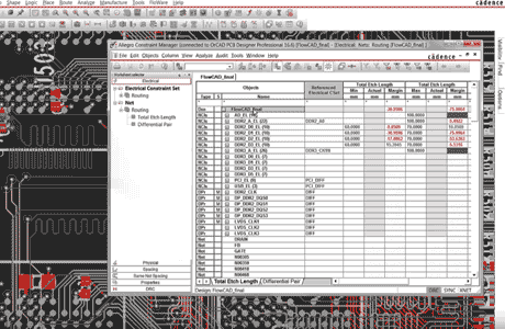
In hierarchical designs the description of a net name might be different. When you import a lower level block, you want to keep signal names unchanged. Whereas in higher levels you might use signal names which corespond with the system architecture. It is important to know, what physical net name is used in the layout as well.

SMART Schematic / Intelligent PDF

SMART Schematic / Intelligent PDF

For documentation a smart or intelligent PDF can be generated from the schematic. This PDF contains net names, properties and constraints which can be searched in Adobe Acrobat Reader.

OrCAD Capture Design Differences

Compare Design Differences

When two versions of a schematic are loaded in OrCAD Capture, the differences between these two designs can be compared. As a result you will see if components are moved or connections are altered.

Altium and Eagle translator

Altium® and Eagle® Schematic Import

Schematics from Altium® and Eagle® can be imported into OrCAD Capture. Symbols can be used and stored in the library. Complete schematics can be imported.
Migration Guide

Arrow reference designs
OrCAD Reference Designs

OrCAD Reference Designs

The parts distributor Arrow® offers more than 10.000 refence designs in OrCAD Capture format. After registration these designs are free to the designer community for download directly into OrCAD Capture. This is a good starting point for new functional blocks.

OrCAD Capture ISO 26262 certified

OrCAD Capture ISO 26262 certified

OrCAD Capture is part of Cadence flows certified to use with ASIL A through ASIL D in automotive design projects. Functional safety documentation kits cover OrCAD Capture for analog, digital, and mixed-signal schematic entry and verification all the way to implementation and signoff in a PCB flow.

TCL Scripting Language

TCL Scripting Language

OrCAD Capture can be customized with TCL-Scripting Language. TCL is a standard programming language in Electronic Design Automation (EDA). There are many TCL commands available and the scripts can be used to perform specific tasks or checks in the schematic.

OrCAD SI Topology
SI Topology Creation

SI Topology

Create a signal integrity tolopology and derive designrules from it to drive a schematic driven PCB layout flow.

XJTAG DFT Assistant für OrCAD Capture

XJTAG DFT Assistant für OrCAD Capture

Mit einer kostenlosen App kann in der Leiterplatten-Entwurfssoftware OrCAD Capture in wenigen Minuten die Test-Coverage der Schaltung angezeigt werden. Die App wurde von XJTAG, einem Anbieter von Boundary-Scan-Hardware und Software-Tools, entwickelt. Mit diesen frühzeitigen Informationen über die Testbarkeit wird ein Design For Test deutlich vereinfacht und so die Anzahl von nachträglichen Änderungen deutlich verringert.
Download DFT App for Capture

Intel Schematic Connectivity Format

ISCF- Export

Für embedded Computer und Internet of Things (IoT)- Anwendungen bietet Intel® einen Design Review Service für seine Kunden an, bei dem die Stromlaufpläne und Layouts auf Übereinstimmung mit den Designregeln überprüft werden. Dieser Service ist für Anwender mit Intel EDC Privileged access möglich. Aus OrCAD Capture kann das spezielle ISCF-Format direkt für flache und hierarchische Schaltpläne ausgegeben werden.

Video Tutorials

See these video tutorials, which explain several technical features in detail:

YouTube Videos

3:02

Why OrCAD

OrCAD Capture is one of the most widely used schematic design solutions for the creation and documentation of electrical circuits. Fast, easy, and intuitive circuit capture, along with highly integrated flows supporting the engineering process, make OrCAD Capture one of the most popular design environments for today’s product creation.

Real-Time Feedback and ECO
1:15

Customize Workspace

Simulating your designs allows you to be aware of the limitations of your components. It’s important to analyze your circuit before moving to layout. Analysis helps identify possible field failures allowing you to reduce development time and cost.

Product feature comparison OrCAD Capture

    OrCAD Capture OrCAD Capture CIS
Graphical, flat, and hierarchical design
Heterogeneous bus and NetGroup support
Dynamically update hierarchical blocks
Design reuse
Heterogeneous and homogeneous parts support
PCB cross probing and cross-placement
Intelligent PDF creation

    OrCAD Capture OrCAD Capture CIS
Flow support for most PCB layout tools
Unlimited undo / redo
Reference external designs and circuits
Tcl-scripting language for customization
Online design rule check
Unlimited user-defined properties
FPGA design-in support
FPGA bi-directional support
Component Information System (CIS)
Centralized part information system CIS option
ODBC-compliant database support CIS option
Relational data support CIS option
MRP, ERP, and PLM integration CIS option
Graphical preview of database parts CIS option
Intelligent database query CIS option
Component property validation CIS option
Temporary new part introduction CIS option
Extensive reports and report templates CIS option
Crystal Reports for advanced documentation CIS option
Assembly Variants
Unlimited assembly variant support CIS option
Part substitution and part "not present" support CIS option
Variant comparison reports CIS option
Print capabilities for variants CIS option
This table is for information only. For details consult the official datasheets from Cadence.

Related Products

OrCAD Capture CIS

OrCAD Capture CIS

Managing Variants and attaching Capture to a ODBC database provides you access to centralized managed libraries. For variants different Bill of Materials (BOM) can be generated to drive pick and placement of components.

more

Library Builder

OrCAD Library Builder

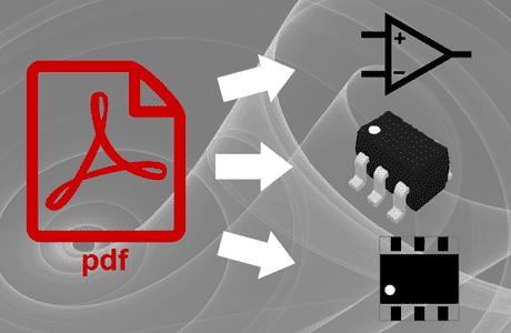
Creating new symbols, Footprints and Step Models with copy and paste directly from a PDF datasheet.

more

UltraLibrarian

UltraLibrarian

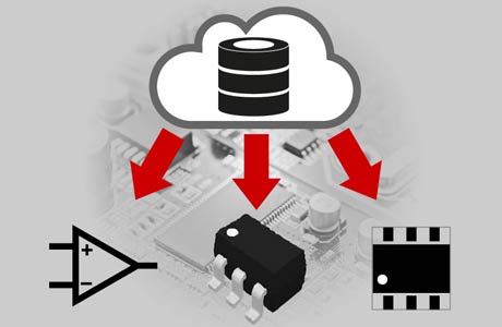
UltraLibrarian is an online library with more than 10M parts. Find the parts you need, download and start designing quickly.

more

PSpice

PSpice Simulator

Circuit simulator to verify functionality, reliability and yield of your circuit directly from the schematic.

more

OrCAD Capture Training Classes

Public training classes are offered on a regular basis. In the table below you will see the time table, when these classes are offered. In addition you can ask for your own training on your site, which makes business sense, when you have five or more person attend the same class form one company. Customization of trainings is possible too.