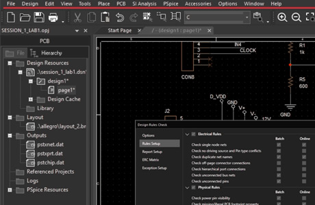
Narzędzie do wprowadzania schematów OrCAD Capture do schematów obwodów jest jednym z najczęściej używanych na świecie programów do wprowadzania i dokumentowania obwodów elektrycznych. To niezwykłe, jak proste i intuicyjne są uchwycone intencje projektowe. OrCAD Capture wykorzystuje płaskie lub hierarchiczne schematy obwodów. Za pomocą okna nawigacji można wybierać różne strony schematu i zarządzać nimi tematycznie.
Za pomocą PartBrowser symbole schematu obwodu wybiera się za pomocą filtrów z biblioteki i umieszcza na schemacie obwodu. Połączenia elektryczne (sieci) między powiązanymi pinami elementów można szybko ustanowić. W przypadku projektów o strukturze hierarchicznej te same sieci elektryczne są wzajemnie połączone za pośrednictwem portów cross-porting lub zdefiniowane jako sieci globalne.
Warianty są definiowane w edytorze schematów, a następnie są wyprowadzane jako warianty z różnymi listami części dla każdego wariantu. W programie OrCAD Capture warianty zespołu można tworzyć za pomocą kilku funkcji logicznych dla płytki drukowanej na podstawie różnych zestawień materiałów dla każdego wariantu. Jeśli w obwodzie stosowane są zaprogramowane elementy, można odczytać przypisania pinów i sygnały z układów FPGA różnych producentów. Obsługuje także metodologię projektowania, która integruje narzędzia dostawców producentów FPGA w miejscu i trasie programowalnych bloków. Zmiany w logice można łatwo zaimportować do schematu obwodu. OrCAD Capture to także moduł do przełączania wejść z list sieci PSpice w celu symulacji obwodów analogowych i sygnałów mieszanych.
W przypadku projektów zawierających programowalne urządzenia (takie jak FPGA) obsługiwany jest przepływ ECO (Engineering Change Order), który synchronizuje różne etapy pracy w narzędziu FPGA, schemacie obwodu i edytorze obwodów drukowanych poprzez adnotację do przodu i do tyłu. Korzystając z opcji CIS, symbole schematów i arkusze danych z internetowych baz danych można umieszczać bezpośrednio na schemacie. Opcja CIS pozwala również na przesyłanie informacji o komponentach z firmowej bazy danych.
OrCAD Capture is one of the most widely used schematic design solutions for the creation and documentation of electrical circuits. Fast, easy, and intuitive circuit capture, along with highly integrated flows supporting the engineering process, make OrCAD Capture one of the most popular design environments for today’s product creation.
OrCAD Capture | OrCAD Capture CIS | ||
---|---|---|---|
Graphical, flat, and hierarchical design | ✓ | ✓ | |
Heterogeneous bus and NetGroup support | ✓ | ✓ | |
Dynamically update hierarchical blocks | ✓ | ✓ | |
Design reuse | ✓ | ✓ | |
Heterogeneous and homogeneous parts support | ✓ | ✓ | |
PCB cross probing and cross-placement | ✓ | ✓ | |
Intelligent PDF creation | ✓ | ✓ |
OrCAD Capture | OrCAD Capture CIS | ||
---|---|---|---|
Flow support for most PCB layout tools | ✓ | ✓ | |
Unlimited undo / redo | ✓ | ✓ | |
Reference external designs and circuits | ✓ | ✓ | |
Tcl-scripting language for customization | ✓ | ✓ | |
Online design rule check | ✓ | ✓ | |
Unlimited user-defined properties | ✓ | ✓ | |
FPGA design-in support | ✓ | ✓ | |
FPGA bi-directional support | ✓ | ✓ | |
Component Information System (CIS) | |||
Centralized part information system | CIS option | ✓ | |
ODBC-compliant database support | CIS option | ✓ | |
Relational data support | CIS option | ✓ | |
MRP, ERP, and PLM integration | CIS option | ✓ | |
Graphical preview of database parts | CIS option | ✓ | |
Intelligent database query | CIS option | ✓ | |
Component property validation | CIS option | ✓ | |
Temporary new part introduction | CIS option | ✓ | |
Extensive reports and report templates | CIS option | ✓ | |
Crystal Reports for advanced documentation | CIS option | ✓ | |
Assembly Variants | |||
Unlimited assembly variant support | CIS option | ✓ | |
Part substitution and part "not present" support | CIS option | ✓ | |
Variant comparison reports | CIS option | ✓ | |
Print capabilities for variants | CIS option | ✓ |
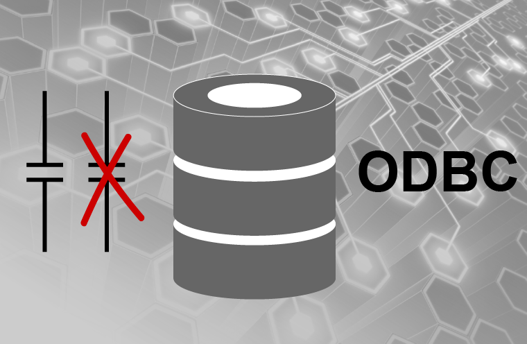
Managing Variants and attaching Capture to a ODBC database provides you access to centralized managed libraries. For variants different Bill of Materials (BOM) can be generated to drive pick and placement of components.
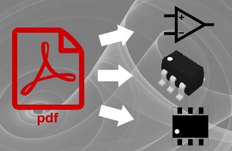
Creating new symbols, Footprints and Step Models with copy and paste directly from a PDF datasheet.
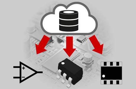
UltraLibrarian is an online library with more than 10M parts. Find the parts you need, download and start designing quickly.
Circuit simulator to verify functionality, reliability and yield of your circuit directly from the schematic.
Public training classes are offered on a regular basis. In the table below you will see the time table, when these classes are offered. In addition you can ask for your own training on your site, which makes business sense, when you have five or more person attend the same class form one company. Customization of trainings is possible too.