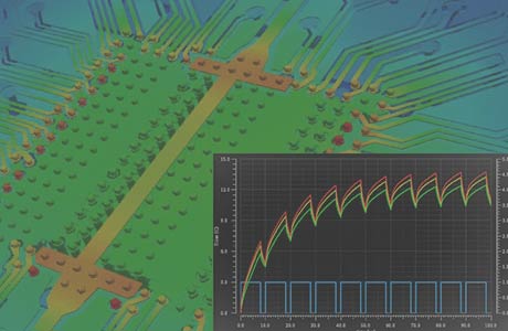
Higher packing densities due to ongoing miniaturization of electronic assemblies lead to heat loss of an electrical circuit which can no longer be dissipated so well. This leads to increased circuit temperatures, which in turn affect the electrical behavior of the used components or the entire electronic assembly. If the component behaves differently with the increased ambient temperature, further local heating can occur, so these effects become complex and the temperature adjusts over time.
Thermal behavior depends on several influences such as the ambient temperature, cooling by convection or additional active cooling and the heat generated by the circuit itself during operation. If a complete simulation of the assembly in operation with all the influences becomes too complex, the simulation can be divided into individual areas. FlowCAD offers different solutions for:
Simulations are possible at different times in the CAD flow. With a rough floor plan, the cooling concept can already be designed with the main components from the parts list. The behavior of individual components can already be viewed on the basis of the circuit diagram and helps with the dimensioning of the components. Temperature changes due to voltage drops on the PCB (IR drop) can be detected and reduced during the layout phase. With the production data, the thermal cooling concept can be verified with different 3D analysis methods (e.g. FEM, Finite Element Method or CFD, Computational Fluid Dynamics).
Each tool is good for one aspect of finding a way to reduce the temperature. The right tool, used at the right time in the design process, brings the desired results early on and avoids unnecessary iterations.
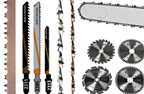
Craftsmen choose the right saw for their project to get the best results. They change tools for different tasks and materials.
The causes and the quality of the cooling for thermal problems on printed circuit boards are diverse. There are different approaches to the solution. Choosing the right tool depends on the problem you are trying to solve. The efficiency and accuracy with which the specifications are achieved are decisive for the criteria when choosing the solution and tool.
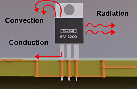
When it comes to heat transfer from an electrical component, there are three physical ways in which the thermal energy is transferred: Conduction is the transfer between solid materials that are in contact. So from the chip to the IC package, the pins / balls to the printed circuit board and the glass / copper mixture (FR-4) to attachments to the housing. Convection is the transmission in liquid and gaseous media, such as air or water. Here the movement away from the hot element and turbulence have to be taken into account. The radiation is electromagnetic thermal radiation with infrared wavelength.
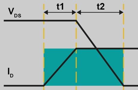
MOSFETs are very efficient, when they are ON with high current or OFF with high voltage. But in the transient phase when switching on or off a MOSFET gets heated due to the losses. The switching frequency is an important factor, how hot the components gets. To describe this behaviour most of the component manufacturer offer a PSpice simulation model. A PSpice simulation will show, how hot the junction temperature inside the MOSFET will be in this particular circuit.
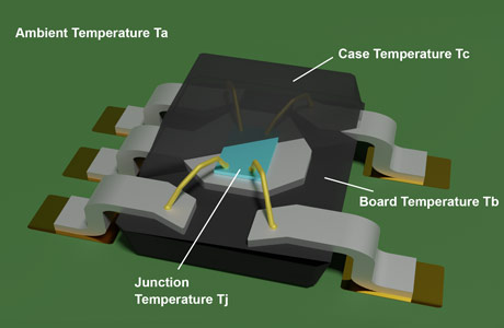
The thermal resistant model describes the heat transfer between parts of the complex thermal system. You can see values for the model from the junction of the die to the outside of the case (Tjc) in a datasheet. These values can be used to model the thermal behaviour.
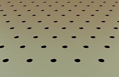
Specific thermal conductivity shows the importance of the continuous metal path from source to drain on and within a circuit board. Copper conducts heat 1000 times better than FR-4. The combination of integrated copper profiles (inlay) with modern circuit board designs such as micro and thermal vias enables direct contact with a soldering surface (components, heatsink). In this way, thermal energy is distributed by conduction and dissipated from the critical components.
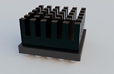
Find the right dimension of a heat sink for critical components in your application. Simple and straight forward inputs make it easy to perform simulations. Just import a step model of the heat sink, assign power (heat) source values and flow conditions, and see the results. Analyze the air flow with natural convection or use a fan to cool heat sinks in 3D orientations for your design. Quickly determine the best cooling method for high power components.
Electrothermal co-simulation considers thermal heating in addition to self-heating. This is the case, when an electronic component i.e. silicon carbide (SiC) metal-oxide-semiconductor field-effect transistor (MOSFET) is used to switch power. The current-voltage characteristic shows a temperature dependency of the drain current and results in power loss of the MOSFET. An electrothermal co-simulation predicts accurate temperatures when the components are used with minimal deviation between measured and simulated results.
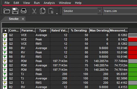
The stress analysis is jokingly called Smoke Analysis, because if there is too much stress, the components "smoke up" due to thermal overload. With this simulation, the maximum de-rating of components can be determined and thus a statement can be made about the component load. The load can be specified as a percentage via the model parameters. The developer is interested in statements about the types of load: thermal at maximum current and highest possible voltage, line of the junction temperature in °C or the thermal contact resistances JC and JA, as shown in occur in the circuit.
More about PSpice
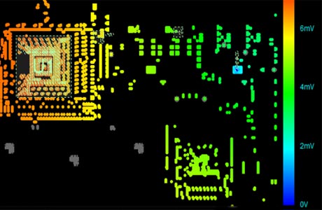
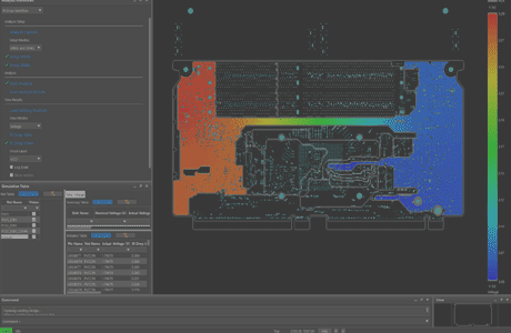
If current travels through a metal with a resistance, there will be a voltage drop. This effect is described by ohms law and is called on PCBs: IR-Drop. In this in-design analysis the resistance of pcb traces and planes will be calculated by a field solver. The results of this simulation, voltage drop, current and current density can be displayed in tables or as color overlays in the design. All this provides valuable information for the PCB designer to improve the design and avoid current hotspots.
Benefits: Stable supply voltage and less thermal issues. Whitepaper IR-Drop
Celsius Thermal Solver seamlessly integrates with Cadence IC, package, and Allegro PCB platforms. Fast and accurate parallel simulation enables new system analysis and design insights and empowers electrical design teams to detect and mitigate thermal issues early in the design process - reducing electronic system development iterations. Engineers can combine Cadence Celsius and Sigrity in an accurate electrical and thermal co-simulation (steady-state and transient) system-level thermal simulation for PCB and IC-Packaging based on the actual flow of electrical power.
More about Celsius
Conduction | Convection | Radiation | |
---|---|---|---|
Meaning | Conduction is a process in which transfer of heat takes place between objects by direct contact | Convection refers to the form of heat transfer in which energy transition occurs within fluid or gas | Radition is heat transferred by an electromagnetic wave with an infrared wavelength |
Represent | How heat travels between objects in direct contact | How heat passes through fluids | How heat flows through empty spaces |
Occurence | In solids, through molecular collisions | In fluids, by actual flow of matter | At a distance and does not heats the intervening substance |
Transfer of heat | Heated solid substance | Intermediate substance | Electromagnetic waves |
Speed | Slow | Slow | Fast |
Law of reflection and refraction | Does not follow | Does not follow | Follow |
Thermal quantities have analogies to those of electrical resistance, which are also reflected in their names. Analogies to electric current appear, which allow the application of Ohm's law and Kirchhoff's rules in heat transfer.
Thermal | Electronic |
---|---|
Absolute thermal resistance Rth | Electric resistance R |
Temperature difference Δ T | Voltage U |
Heat flow Q | Current I |
Thermal conductivity λ | Electric conductivity σ |
Heat capacity Cth | Electric capacity C |
Material | Thermal Conductivity λ [W / (m * K)] |
---|---|
Gold | 314 |
Silver | 429 |
Copper | 380 - 400 |
Aluminum | 200 - 240 |
Air | 0.0262 |
FR-4 | 0.2 - 0.25 |
Silicon | 148 |
Brass | 120 |
Solder | 50 |