Sigrity Aurora

Cadence Sigrity Aurora provides traditional signal and power integrity (SI / PI) analysis for pre-layout, in-design, and post-layout PCB designs. Integrated with Cadence OrCAD and Allegro PCB editing and routing technologies, Sigrity Aurora users can start analyzing early in the design cycle using “what if” exploration scenarios in order to set more accurate design constraints and reduce design iterations. Power Feasibility Editor helps to select the right combination of decoupling capacitors in pre-layout.
Sigrity Aurora reads and writes directly to the Allegro PCB database for fast and accurate integration of design and analysis results. It provides a SPICE-based simulator and the patented Sigrity embedded hybrid field solvers for extraction of 2D and 3D structures. It supports power-aware default model library, IBIS (behavioral) models, as well as transistor-level models, if necessary. High-speed signals can be explored pre-layout, to compare alternatives, or post-layout, for a comprehensive analysis of all associated signals.
Key Benefits- Detects SI and PI design errors early to reduce design re-spins and increase first-pass success
- Explores alternative topologies in the earliest stages
- In-design analysis provides guidelines to minimize EMI already during PCB layout phase, specifically created for PCB designers
- Tightly integrates Sigrity analysis engines with OrCAD and Allegro PCB Editor
- Provides quick screening of a design for SI problems without the need for SI models
- What-if topology circuit simulation using the modern Allegro system capture canvas
- Provides in-design SI / PI analysis within a constraint-driven flow
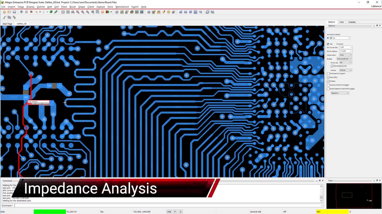
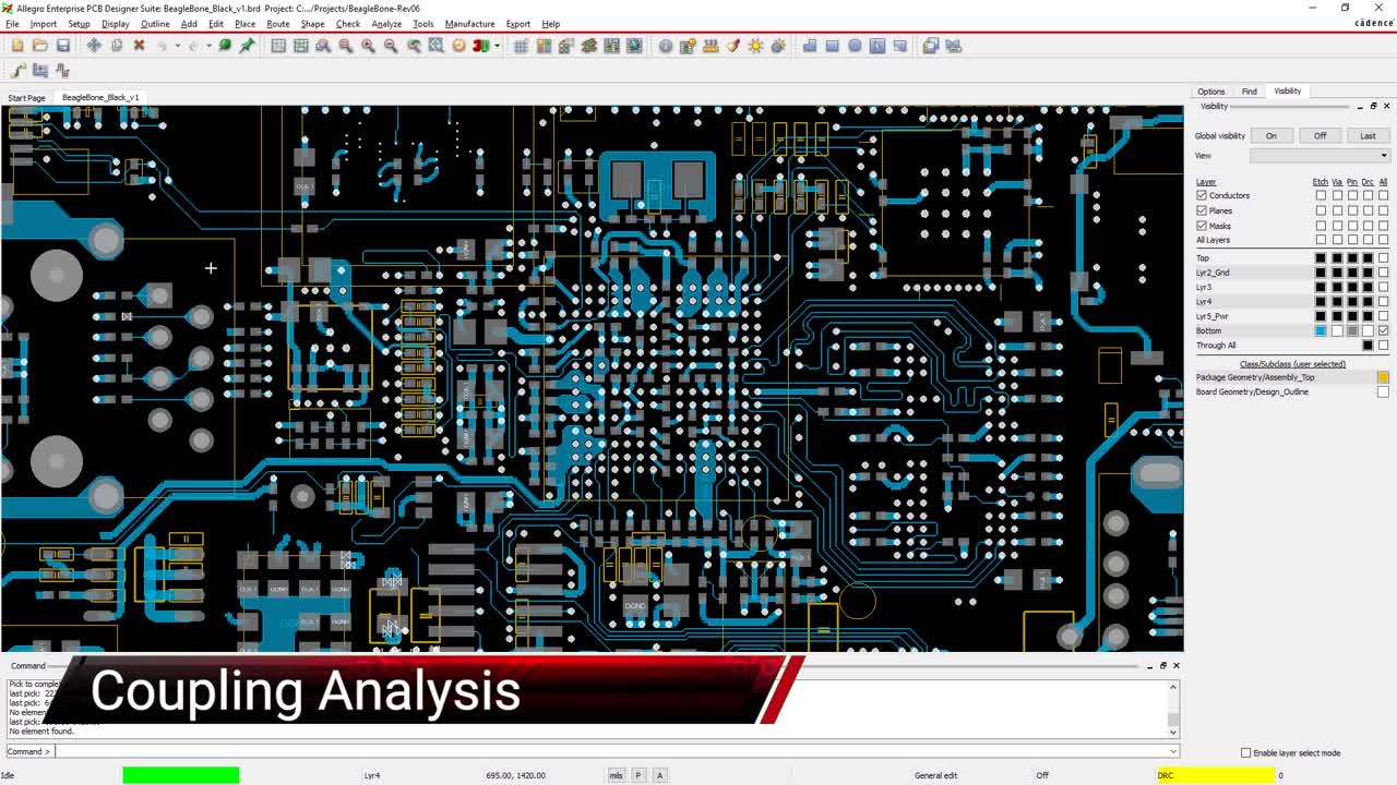
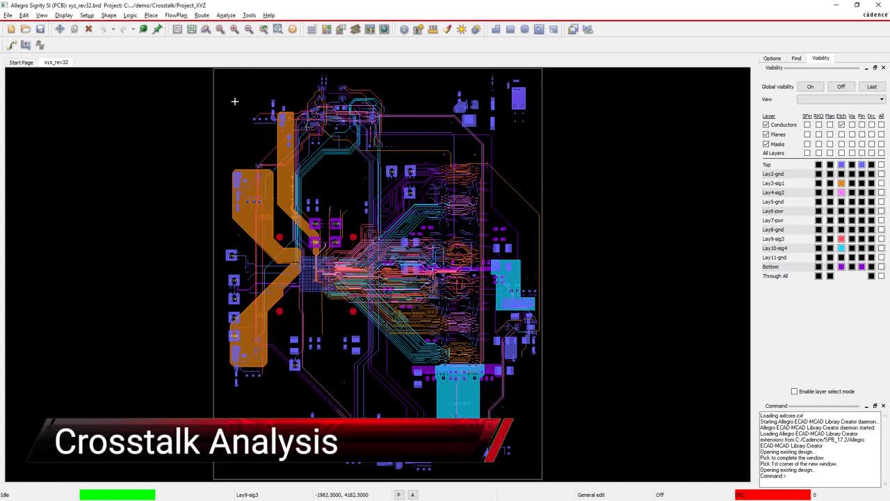
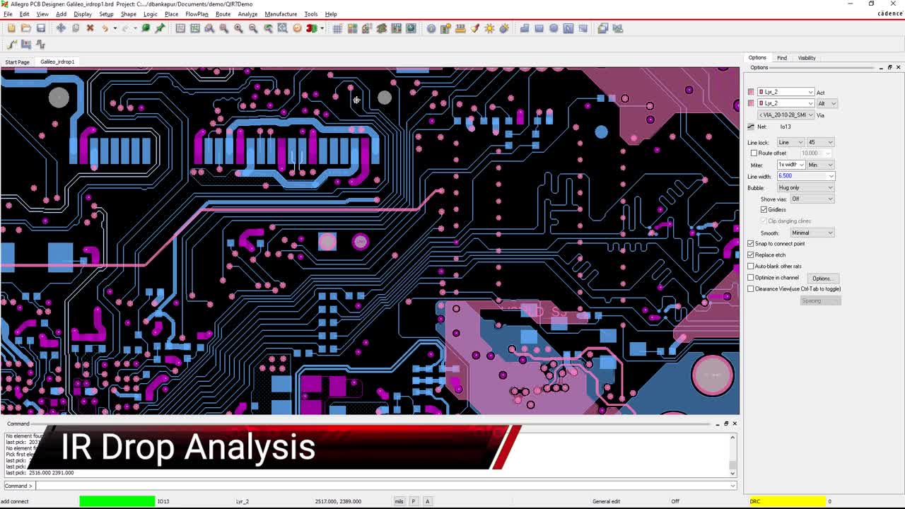
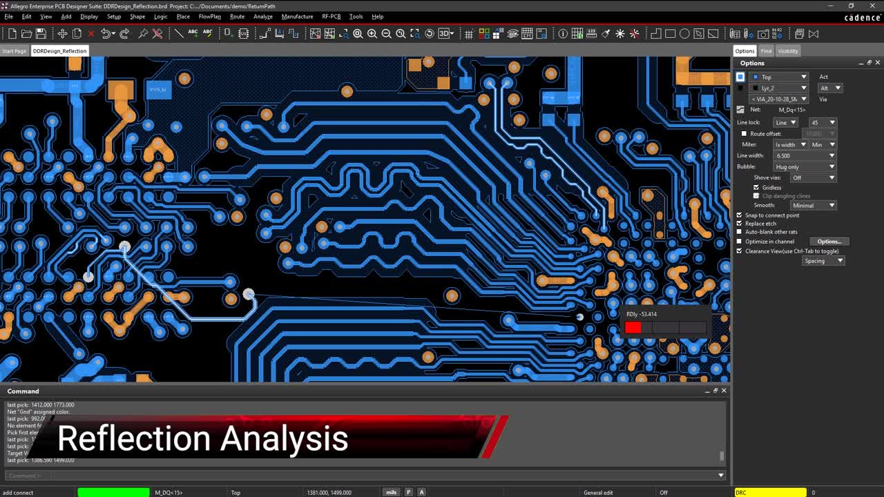
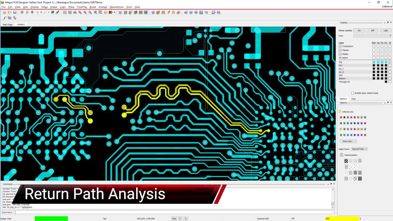
- Impedance discontinuities, coupling, crosstalk, reflections, IR-drop, and return path analysis
- Support of live Allegro PCB Symphony Team Design session to perform SI / PI analysis without making a copy of the design