AWR Microwave Office

AWR Microwave Office

Microwave Office allows you to create complex circuit designs for high-frequency electronics composed of linear, nonlinear, and electromagnetic (EM) structures with a high degree of design automation. Easily build your schematic from a component library, define component parameters and generate a RF-aware layout representation in one environment.

Perform fast and accurate analysis of your design using linear, and nonlinear effects (Volterra-series), electromagnetic (EM), and harmonic balance analysis of extremely nonlinear circuits (APLAC) or use other simulation engines if needed.

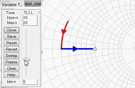
Microwave Office has real-time tuning and optimizing capabilities. After an initial simulation you can change the parmeters with a slider and see direct feedback of the curves.

Demand for increased functionality is driving more complex structures in modern high-frequency printed-circuit boards (PCBs) like:

  • RF devices (i.e. Amplifiers, Filters)
  • Radar
  • Communication applications
  • PCB analysis of surface-mount components
  • Interconnecting transmission lines
  • Embedded and distributed passive elements

Microwave Office offers a layout-driven design methodology for complex RF PCBs that supports accurate modeling of PCB transmission media from the RF-signal path to digital control and DC-bias lines.
Circuit Design Software That Delivers Accurate Simulation for RF / Microwave Product Development

Features of AWR Microwave Office

Layout-driven PCB Design

Layout-driven PCB Design

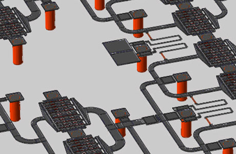
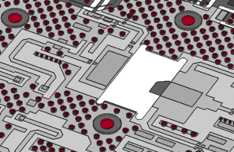
Layout-driven PCB design supports accurate simulation of the entire RF signal path, including EM co-simulation for analysis of complex electrical interconnects as well as embedded and distributed passive elements. AWR Microwave Office circuit simulation provides designers with rapid design entry / editing that automatically resizes junction and discontinuity models as circuits are tuned, optimized, or re-routed, all without changing the schematic. A layout net, represented as a “rat’s nest,” is selected in the layout and then routed simply by clicking the path from component to component.

Optimization and Visualization
Optimization and visualization

Optimization and Visualization

Designing a RF circuit is an interactive process, where you need to change the parameters of your design and see the impact visualized in various plots. By changing parameters with sliders you see the immediate effect on your result, no matter if it is a rectangular, smith chart, polar, histogram, antenna plot, tabular, constellation, or 3D plot. This interactive approach guides you quickly to the desired function of your design.

Tool Interoperability

Tool Interoperability and Design Flow Automation

AWR products provide compatibility with many PCB file formats. PCB layout information can be exchanged with a variety of PCB tools like Allegro, OrCAD, Altium, Intercept, Siemens - Mentor Graphics, Zuken, and more by DXF, Gerber, ODB++, and IPC-2581. AWR Connected allows to use alternative EM or thermal simulators.

iFilter
iFilter

iFilter

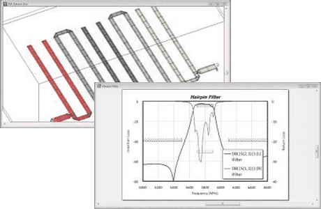
iFilter is an add-on synthesis module for developing RF / microwave filters to accelerated filter design. The iFilter integrated filter synthesis wizard runs seamlessly within the AWR Design Environment platform. It enables filter designers to accelerate design starts with powerful synthesis of lumped- and distributed-filter types, supporting export of resulting circuit topologies directly into Microwave Office for further refinement, optimization, electromagnetic (EM) verification and physical design.
iFilter Datasheet

MMIC (III-V Semiconductor)

MMIC (III-V Semiconductor)

Monolithic microwave integrated circuit (MMIC) are semiconductors build from materials of the chemical columns of the periodic system III and V like i.e. GaAs, GaN or InP. MMICs offer superior RF performance for RF amplifiers and 5G communications infrastructure. Microwave Office helps to achieve optimal performance by reliable 3D circuit simulation, electromagnetic (EM) verification, communications test benches, and a design flow that links electrical design to physical realization.
AWR Microwave Office for MMIC Datasheet

AWR Free Trial

Test the various possibilities of AWR free of charge for 15 days. Please fill out the form below as completely as possible.

After submitting the form, FlowCAD will contact you and discuss the further details. Together you will select the appropriate AWR expansion level for your needs (Linear / Nonlinear, Base Functions, Planar EM, etc).
Your host ID is required to create the license. You have the option of specifying the start date of your trial version, or alternatively we can make a time proposal.
Our support team will then be happy to help you with the installation and answer any questions you may have.