Increasing use of standards-based advanced interfaces such as DDR3, DDR4, PCIe, USB 3.0 are bringing a set of constraints that must be adhered to while implementing a PCB. The Allegro PCB Designer High-Speed Option makes adhering to constraints on advanced interfaces quick and easy. It offers an extensive range of electrical rules to ensure that the PCB design implementation is complaint with the specification for advanced interfaces. Additionally, it allows users to extend the rules through the use of formulas with existing rules or post-route data such as actual trace lengths.
The High-Speed Option allows users to apply a topology to a set of signals. A topology can include a set of routing preferences as well as constraints such as putting the termination resistor closer to either the driver or a receiver on a signal. The constraint-driven PCB design system then provides feedback through the constraint manager if a signal doesn’t conform to the topology or the rules associated with the topology, ensuring that issues are identified (and therefore can be addressed) as quickly as possible. The High-Speed Option also enables checking of delays through vias, connector pins, and IC package-pin for die2die length/delay matching. It includes, utilities to identify trace segments crossing voids (return path issues that cause re-spins), supports back drilling (remove through hole antennas) as well as provides a timing environment that can accelerate timing closure of critical nets up to 60-70% .
More functionality in Constraint Manager for reflection, timing and crosstalk.
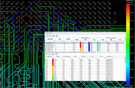
Timing Vision is an innovative and unique environment that allows users to graphi-cally see real-time delay and phase infor-mation directly on the routing canvas. Traditionally, evaluating current status of timing/length of a routed interface requires numerous trips to Constraint Manager and/or use of the Show Element command. Using an embed-ded route engine to evaluate complex timing constraints and interdependen-cies amongst signals shows current status of a set of routed signals—a DDRx byte lane or a complete DDRx interface—via custom trace/connect line coloring; stipple patterns and customized data tip information to define the delay problem in the simplest terms possible.With the embedded route engine, Timing Vision provides real-time feedback to the user during interactive editing and enhances the user’s ability to develop a strategy for resolving timing on large buses or interfaces such as DDRx, PCIe, etc.
High-Speed via structures allows you to create reusable multi-net elements where you can define correct-by-design high speed via transitions with return path vias and custom voids (as route keepouts). The tool allows you to identify which are return path vias and assign return net during placement. When routing high speed signals an impedance discontinuity exists at a via. When aleays the same via structure is used, the impact of the discontinuity is predictable. Stuctures can be optimized with 3D simulations.
Impedance Workflow, Coupling Workflow, Crosstalk Workflow, Reflection Workflow, IR Drop Workflow, Returnpath Workflow Sigrity Installation braucht man immer. Nur Impedance und Coupling geht ohne Sigrity Lizenz. Die anderen Workflows checken Sigrity oder Aurora aus.
Tabbed routing is a new routing strategy in which trapezoidal shapes called tabs are added to parallel traces to control impedance in the pin field/breakout region, and crosstalk in open field region allowing for longer trace lengths and use of smaller trace spacing.
AiDT Delay tuning for signals for interfaces like DDRx takes up too much time when using traditional, manual methods. AiDT auto-matically generates tuning patterns on a user-selected routed byte lane or interface based on user-defined timing constraints and tuning parameters. AiDT computes the required length for the connections to meet timing constraints and utilizes controlled push/shove techniques when adding tuning patterns (see Figure 7).
AiPT Differential pairs in an interface like DDRx require designers to match static as well as dynamic phase. Matching phase for all differential pairs in an interface is a neces-sary first step before tuning and matching the rest of the signals. AiPT automatically matches dynamic and static phase for the selected differential pairs. It works with a set of parameters that allows the user several options for trace lengthen-ing or shortening as well as pad entry/exit options. With AiPT, users can significantly shorten the time to match static and dynamic phases for differential pairs.
Desired state – ACC handles primary effort, Consolidated table based constraints, Value data mining during compilation: Compilation wizard, Flexible table formats, Consistent process for creation, updates and reuse, Reduce human efforts to mapping data and controlling ACC operations
Im Film wird gezeigt, dass unterschiedliche Längen eines differentiellen Paares zu einem Phasenversatz führen. Dieser wird mit Timing Vision anschaulich gemacht und anschließend mit der Funktion Auto interactive Phase Tune (AIPT) gezielt ausgeglichen: