AWR Microwave Office

AWR Microwave Office

Mikrovlnná kancelária vám umožňuje vytvárať komplexné návrhy obvodov pre vysokofrekvenčnú elektroniku zloženú z lineárnych, nelineárnych a elektromagnetických (EM) štruktúr s vysokým stupňom automatizácie návrhu. Jednoducho zostavte svoju schému z knižnice komponentov, definujte parametre komponenty a vygenerujte zobrazenie rozloženia RF-aware v jednom prostredí.

Vykonajte rýchlu a presnú analýzu svojho návrhu pomocou lineárnych a nelineárnych efektov (séria Volterra), elektromagnetického (EM) a harmonického vyváženia extrémne nelineárnych obvodov (APLAC) alebo podľa potreby použite iné simulačné motory.

Mikrovlnná kancelária má možnosti ladenia a optimalizácie v reálnom čase. Po počiatočnej simulácii môžete zmeniť parametre pomocou jazdca a zobraziť priamu spätnú väzbu kriviek.

Dopyt po zvýšenej funkčnosti vedie k zložitejším štruktúram moderných vysokofrekvenčných dosiek s plošnými spojmi (PCB), ako sú:

  • RF zariadenia (t. J. Zosilňovače, filtre)
  • Radar
  • Komunikačné aplikácie
  • PCB analýza povrchových komponentov
  • Prepojovacie vedenia
  • Vložené a distribuované pasívne prvky

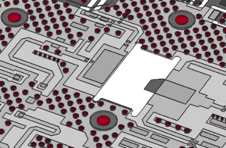
Microwave Office ponúka metodológiu návrhu založenú na usporiadaní komplexných RF PCB, ktorá podporuje presné modelovanie prenosových médií PCB od cesty RF signálu k digitálnemu riadeniu a linkám so skreslením DC.

Softvér obvodového dizajnu, ktorý poskytuje presnú simuláciu pre vývoj produktov RF / mikrovln

Features of AWR Microwave Office

Layout-driven PCB Design

Layout-driven PCB Design

Layout-driven PCB design supports accurate simulation of the entire RF signal path, including EM co-simulation for analysis of complex electrical interconnects as well as embedded and distributed passive elements. AWR Microwave Office circuit simulation provides designers with rapid design entry / editing that automatically resizes junction and discontinuity models as circuits are tuned, optimized, or re-routed, all without changing the schematic. A layout net, represented as a “rat’s nest,” is selected in the layout and then routed simply by clicking the path from component to component.

Optimization and Visualization
Optimization and visualization

Optimization and Visualization

Designing a RF circuit is an interactive process, where you need to change the parameters of your design and see the impact visualized in various plots. By changing parameters with sliders you see the immediate effect on your result, no matter if it is a rectangular, smith chart, polar, histogram, antenna plot, tabular, constellation, or 3D plot. This interactive approach guides you quickly to the desired function of your design.

RF Schematics
RF Schematics

RF Schematics

Capture quickly the design intent with parametric components from the library. By changing the parameters of the components, the shape and dimensions of the metal structure will be adjusted in the RF-aware layout. Sweeping parameters in simulations guides you quickly to the desired behaviour of your circuit. iNet (intelligent net) technology automates layout implementation of interconnects as wires on a schematic.

Tool Interoperability

Tool Interoperability and Design Flow Automation

AWR products provide compatibility with many PCB file formats. PCB layout information can be exchanged with a variety of PCB tools like Allegro, OrCAD, Altium, Intercept, Siemens - Mentor Graphics, Zuken, and more by DXF, Gerber, ODB++, and IPC-2581. AWR Connected allows to use alternative EM or thermal simulators.

iFilter
iFilter

iFilter

iFilter je přídavný syntetický modul pro vývoj RF / mikrovlnných filtrů pro urychlení návrhu filtrů. Průvodce integrovanou syntézou filtrů iFilter běží hladce v rámci platformy AWR Design Environment. Umožňuje návrhářům filtrů, aby urychlili návrh, počínaje silnou syntézou typů soustředěných a distribuovaných filtrů, podporující export výsledných obvodových topologií přímo do Microwave Office pro další upřesnění, optimalizaci, elektromagnetické (EM) ověření a fyzický návrh.
iFilter Datasheet

MMIC (III-V Semiconductor)

MMIC (III-V Semiconductor)

MMIC (Monolitic Microwave Integrated Circuit) jsou polovodiče vyrobené z materiálů periodické tabulky III a V, např. Konstruují se GaAs, GaN nebo InP. MMIC poskytují vynikající výkon pro vysokofrekvenční zesilovače a 5G komunikační infrastrukturu. Mikrovlnná kancelář přispívá k optimálnímu výkonu, včetně prostřednictvím spolehlivé simulace 3D obvodu, elektromagnetického ověření, testovacích lavic komunikace a konstrukčního toku, který spojuje elektrický design s fyzickou implementací.
AWR Microwave Office, MMIC list

AWR Free Trial

Test the various possibilities of AWR free of charge for 15 days. Please fill out the form below as completely as possible.

After submitting the form, FlowCAD will contact you and discuss the further details. Together you will select the appropriate AWR expansion level for your needs (Linear / Nonlinear, Base Functions, Planar EM, etc).
Your host ID is required to create the license. You have the option of specifying the start date of your trial version, or alternatively we can make a time proposal.
Our support team will then be happy to help you with the installation and answer any questions you may have.