Allegro System Capture
Allegro System Capture

Define the architecture of a design with a smooth implementation to create a product that meets cost, performance, and formfactor requirements. Cadence Allegro System Capture is a scalable and easy-to-use solution for fast design intent creation that allows the high-level system architecture and functional diagram to stay connected to the detailed implementation of each board.

Start with definition and functional block diagrams to define the architecture of your electronic set-up and apply design constraints on system level as needed. Use hierarchical blocks to partition your design and generate designs context for multiple printed circuit boards in a framework and keep them all in sync. All settings are available in preferences dialog box for configuration.

  • System Definition and Functional Block Diagrams
  • Partitioning and Assembly Integrity
  • System Connectivity Integrity
  • Signal Traceability
  • Schematic Validation
  • Concurrent Team Design
  • Reliability Analysis without Models
Allegro System Capture Datasheet
System Architecture Design and Implementation for Multi-Board PCB Systems

Product Features

Schematic Entry
Schematic Entry

Schematic Entry

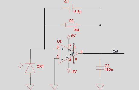
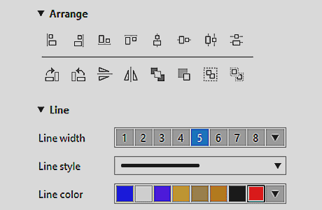
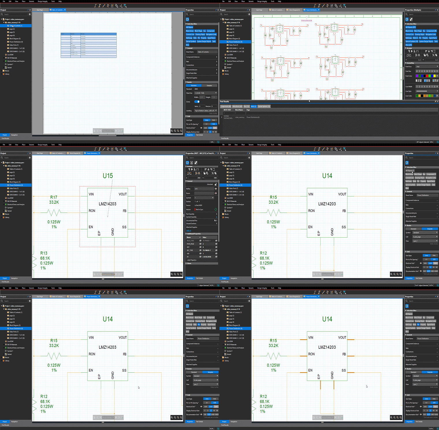
From a single schematic page to a complex electronic system, Allegro System Capture has all capabilities to quickly capture the design intent and design rules of a electronic circuit. This modern tool was developed to have a fast learning curve and intuitive use model to make even developers productive who capture circuits only a few times per year. Documentation of the schematic looks professional due to many styling possibilities like TrueType fonts, line styles and colors as well as many drawing features.

Drawing Capabilities

Drawing Capabilities

Drawing on a canvas is optimized for electrically correct and visually structured schematics. With grid snaping and alignment features the part placement is guided. Connecting wired will be interactively routed. Connecting busses is possible by hovering pins of components and suitable connections are made in parallel with only a few clicks. The arrangement of decoupling capacitor fields will automatically arrange as a matrix and all power / ground wires are automatically updated. Well defined and comprehensive rules to detect all possible legal and illegal connectivity shorts.

Design Constraint Management

Design Constraint Management

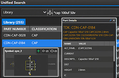
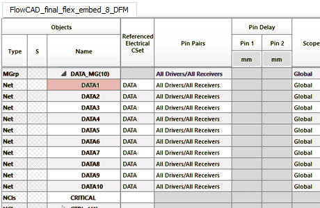
Design Constraints might be due to the electrical behaviour and should be captured as early as possible. If an engineer selects a part, the design rules for this component are describes in the datasheet and can be entered while placing the part on the canvas. The integrated topology exloprer provides a signal based view, which makes it easy to apply constraints to signals, busses or netgoups.

Reliability Analysis
Reliability Analysis without models

Reliability Analysis without Models
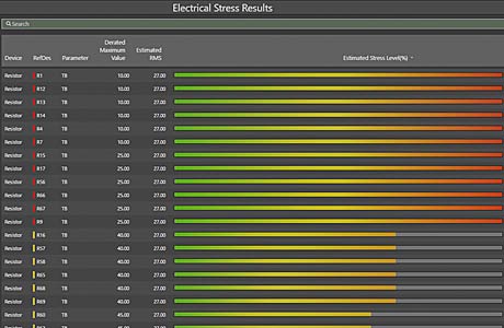
In a schematic audit you can verify with 30+ rules the integrity of your schematic for net-connectivity, part-properties and component-values and cross-probe to instances and nets to fix warnings and errors. Electrical overstress analysis based just on the schematic verifies electrical stress for each device in the design and visualize stress reports with different derating. With schematic ERC basic connectivity checks are performed for schematic grammatic correctness.
More

Data Management
Data Management - Version on Save

Data Management - Version on Save

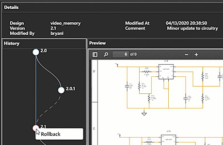
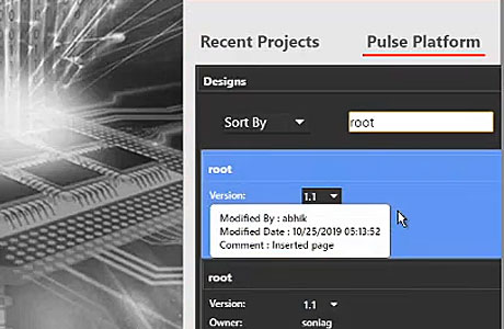
Data is managed transparent to the user with “save”. User can optionally create “commit” points or add simple branching. Data management offers an intuitive rollback with preview of any version without opening. In a shared environment, previews are available via a browser. Data is indexed for analytics and search.

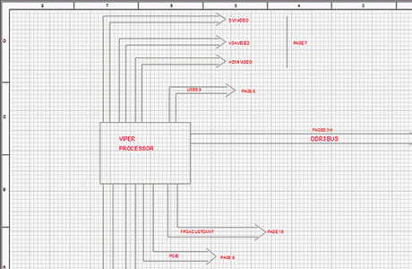
System Definition and Functional Block Diagrams

System Definition and Functional Block Diagrams

Entering the block level diagram in Allegro System Capture puts all information in one place and synchronized. In addition to Microsoft Visio or PowerPoint you can add interface specifications or organize the partitioning into multiple PCBs in one tool. If you want to reuse existing elements of previous designs you can do so by just importing the design and using the connector information. Allegro System Capture is creating a functional block diagram that can be linked to the detailed implementation.

Team Design Collaboration
Ad-hoc Team Design

Ad-hoc Team Design

System design authoring is a team effort and multiple design engineers can collaborate asynchronously in the hierarchical development of a system’s definition. A schematic can be partitioned into user-defined levels of hierarchy and distributed to the defined members of the engineering team, providing them with an isolated “sandbox” for the development and verification of their partition(s). Allegro System Capture provides team assignment and notification capability to assign engineers to specific blocks they are responsible for. It provides a dashboard view of the current status of each team member’s block. This solution provides much-needed flexibility for large time-critical projects while accelerating the design creation process.