OrCAD PCB Designer Standard

OrCAD PCB Design

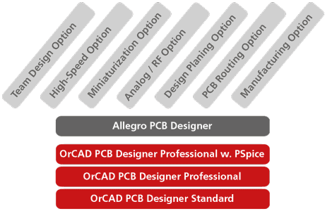
OrCAD PCB Designer Standard is a software package, which offers a very favorable entry into professional printed circuit board design with a price of 2.500 € (including 1 year maintenance). The PCB software already has the schematic entry module OrCAD Capture and OrCAD PCB Editor with integrated Constraint Manager. The scalable OrCAD / Allegro PCB platform provides investment protection for the user, as increasing technical requirements based on the same data base can be used to upgrade to more powerful Allegro licenses.

OrCAD PCB Designer Standard includes the following functionality:
  • Vendor neutral data export with IPC-2581
  • 3D Step file export to mechanical CAD
  • 3D Viewer for visualization and collision check
  • IDX interface to eCAD-mCAD data exchange flow
You want to switch to OrCAD PCB Designer Standard?
Video Highlights
Product Features
Video Tutorials
Comparison Table
Related Products
Youtube Videos

Professional PCB Design, Board Layout & Routing

The Allegro engine powers OrCAD and your productivity. OrCAD comes with PCB layout, high-speed routing and real-time electronic design feedback. To produce a manufacturable board design faster.

Real-Time Constraint Driven Interactive Routing

Real-Time Constraint Driven Interactive Routing

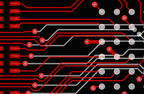
Even the most complex routing is easy with real-time constraint driven feedback tips to help you make a manufactuable and functional PCB.

Dynamic shapes

Effortless Shape Creation and Management

Dynamically update shapes instantly without waiting to repour polygons when you resize, reshape, and plow through shapes when routing.

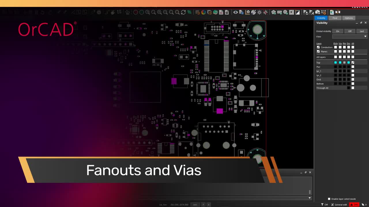
Auto-Assisted BGA Fanouts and Via Creation

Auto-Assisted BGA Fanouts and Via Creation

The repetitive nature of BGA and other high pin-count device fanouts is perfect for time-saving automation to make you more productive.

Product Features

OrCAD Capture
Schematic Entry OrCAD Capture

Schematic Entry with OrCAD Capture

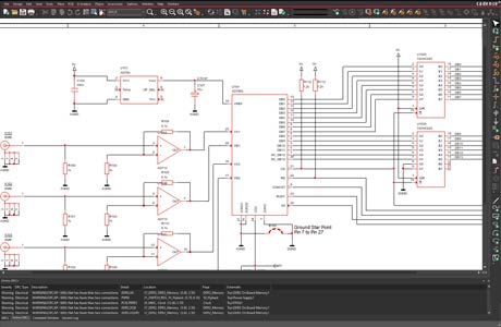
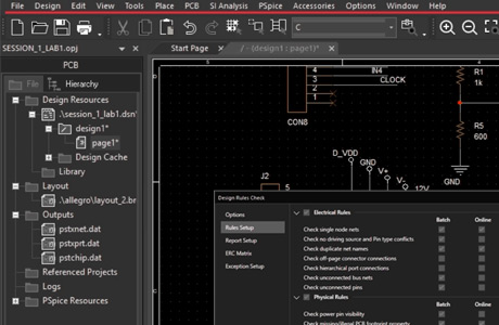
OrCAD Capture schematic entry tool for circuit diagrams is one of the world's most widely used software for entering and documenting electrical circuits. OrCAD Capture uses flat or hierarchical schematics. Via the navigation window the different pages of the schematic can be selected and thematically managed according to functional blocks. By using the integrated interface, it is also possible to use parts from Ultra Librarian and SamacSys, which offer millions of components. The electrical connections between the component pins can be established quickly and rules can already be defined on schematic level.
Learn More

PCB Editor
PCB Editor

PCB Editor for Physical Layout

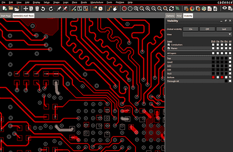
PCB Editor is the canvas to perform PCB layout. With many automated functions the designer can efficiently implement the physical design with traces, planes, component footprints, drill holes, etc. While working with automated assistance, design rule checks in real time help to follow design rules and implement the design intent ready for PCB production quickly. Interactively working in 2D and 3D offers advantages depending on the task.

SPECCTRA auto router

SPECCTRA auto router (6 Layers)

The SPECCTRA auto router can help to complete the routing of a PCB with up to 6 signal layers. Selecting a net or a group of nets gives the user control, which nets are routed automatically. To influence the layout several parameters can be adjusted, such as fanout and routing direction. A router might not do the complete board, but when used wisely it supports the PCB designer to finish digital elements with constraints faster. Feasibility studies are done in minutes and give an indication, if the board is routable with this number of layers. Auto-interactive routing commands support the user in manipulation the automatically done routing.

OrCAD Scalability
OrCAD Scalability

OrCAD Scalability

OrCAD PCB Designer is based on Allegro PCB design technology and both (OrCAD and Allegro) use the same design database. The difference in the licenses is the feature set how to automatically edit and verify the design. The number of design rule checks varies by the type of license. The big advantage is, that you only pay for the functionality you need. When working in a team with multiple licenses, you can check out and use the license you need to perform a certain task or check. All information is stored in the same database.

Online Design Rule Check DRC
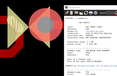
DRC Error

Online Design Rule Check DRC and DFM Checks

During routing, the tool checks whether design rules are violated in real-time. When errors are caused, e.g. by placing a component in an unauthorized location, the tool will highlight a design rule violation. All rules defined in Constraint Manager can be checked. Unique for PCB layout tools are the more than 250 integrated DFM checks, which check against specifications of the PCB fabricator, assembly service provider or test facility, by automatically reading in their rules sets.

Constraint Manager
Constraint Manager

Constraint Manager (basic)

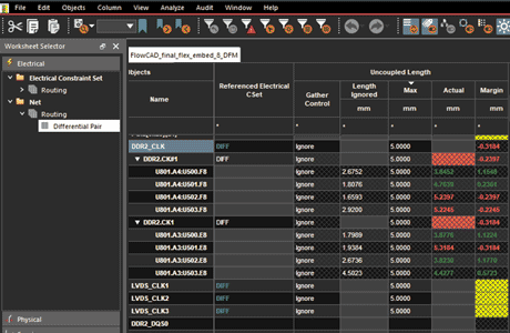
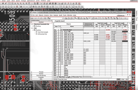
OrCAD PCB Designer Standard has already a fully integrated Constraint Manager in OrCAD Capture and OrCAD PCB Editor. It makes it easy to define design rules and assign topologies in a central place. The rules are hierarchically defined and can be assigned to a number of nets at the same time. With design rule sets as constraint sets (CSet), several rules can be summarized and reapplied in subsequent designs. OrCAD PCB Designer Standard can manage a variety of physical, spacing and DFM rules. During engineering review all the rules are visible in one view next to each other and wrong rules stand out. more

SI Simulation
SI Simulation

Signal Integrity (SI) Simulation (basic)

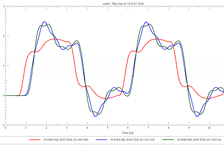
Clicking on a net in the schematic can open the simulation for signal integrity. By changing the length or impedance, the signal quality can be analysed. IBIS models can be used for driver and receiver components when available, otherwise Cadence default models can be used with parameters from the datasheet.

PSpice Integrated on OrCAD PCB Flow

PSpice Integrated on OrCAD PCB Flow

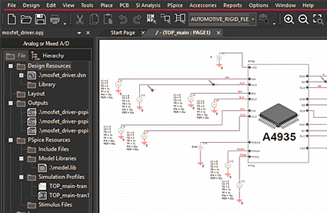
Basic functionality of PSpice is integrated in the OrCAD PCB design flow. Design intend is entered in schematic entry tool OrCAD Capture and can be used to drive a PSpice simulation and develop functionality of the circuit. Same schematic can be used for documentation and simulation. The netlist can be created and the PCB Editor uses the schematic to cross probe during placement and routing. A comprehensive integration provides broad information and avoids errors in the design process.
PSpice Feature comparison

Video Tutorials

See these video tutorials, which explain several technical features in detail:

Product Feature Comparison for OrCAD PCB Designer

    OrCAD PCB Designer Standard OrCAD PCB Designer Professional OrCAD PCB Designer Professional with PSpice
OrCAD Capture
PCB Editor
SPECCTRA auto router -
Scalable to Allegro
DFM rules checks 250 250 250
Constraint Manager basic
SI simulation basic
Electrical Rule Check (ERC) -
High-speed DRC -
PSpice simulation basic basic PSpice A/D + Smoke
This table is for information only. For details consult the official datasheets from Cadence.

Related Products

CAD-FlowManager

CAD-FlowManager

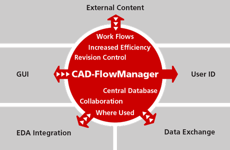
Manage work flows for library components or complete designs and integrate into PLM or other databases.

More

Library Builder

OrCAD Library Builder

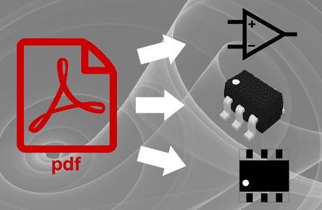
Creating new symbols, Footprints and Step Models with copy and paste directly from a PDF datasheet.

more

UltraLibrarian

UltraLibrarian

UltraLibrarian is an online library with more than 10M parts. Find the parts you need, download and start designing quickly.

more

PSpice

PSpice Simulator

Circuit simulator to verify functionality, reliability and yield of your circuit directly from the schematic.

more

YouTube Videos

3:02

Why OrCAD

OrCAD Capture is one of the most widely used schematic design solutions for the creation and documentation of electrical circuits. Fast, easy, and intuitive circuit capture, along with highly integrated flows supporting the engineering process, make OrCAD Capture one of the most popular design environments for today’s product creation.

Real-Time Feedback and ECO
1:15

Customize Workspace

Simulating your designs allows you to be aware of the limitations of your components. It’s important to analyze your circuit before moving to layout. Analysis helps identify possible field failures allowing you to reduce development time and cost.